Motor FLA Calculator
A motor FLA calculator estimates the Full Load Amps (FLA) of an electric motor based on horsepower, voltage, phase type, efficiency, and power factor. Enter your motor specifications in the panel to calculate the expected current draw for wire sizing, breaker selection, and electrical planning.
What Is Motor FLA?
Full Load Amps Definition
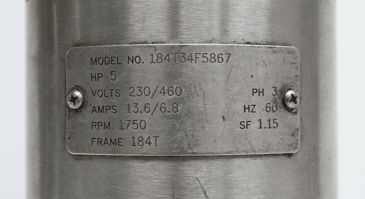
Full Load Amps (FLA) is the amount of current, measured in amperes, that an electric motor draws when operating at its rated horsepower output under full load conditions. FLA is listed on the motor nameplate and represents the maximum continuous current the motor is designed to carry without overheating under normal operating conditions. It is the baseline value used to size all motor circuit components, including conductors, overcurrent protection, and motor starters.
FLA differs from locked rotor amps (LRA) and service factor amps (SFA). LRA is the high inrush current drawn when the motor first starts, typically 6 to 8 times the FLA. SFA is the current drawn when the motor operates at its service factor rating, which is a percentage above rated load that the motor can sustain for short periods without damage.
Why FLA Matters
FLA is the most critical value for motor circuit design under the National Electrical Code (NEC). The NEC requires that motor branch circuits be sized based on FLA rather than the actual measured current. Conductors must have an ampacity of at least 125% of the motor FLA per NEC Section 430.22. Overcurrent protection devices such as circuit breakers are sized as a percentage of FLA per NEC Table 430.52. Overload relays in motor starters are also set based on FLA to protect the motor windings from sustained overcurrent.
How to Calculate Motor FLA
Single Phase FLA Formula
For single-phase motors, the FLA formula is derived from the electrical power equation, where power in watts equals voltage times current times efficiency times power factor:
- HP — Motor horsepower rating
- 746 — Watts per horsepower conversion factor
- V — Supply voltage in volts
- Efficiency — Motor efficiency as a decimal (e.g., 85% = 0.85)
- Power Factor — Motor power factor as a decimal (typically 0.80 to 0.95)
Example: A 2 HP, 120V single-phase motor with 85% efficiency and 0.85 power factor draws approximately (2 × 746) / (120 × 0.85 × 0.85) = 1,492 / 86.7 = 17.2 amps at full load.
Three Phase FLA Formula
Three-phase motors use the same base formula, but include the square root of 3 (1.732) to account for the three-phase power factor:
Example: A 10 HP, 460V three-phase motor with 90% efficiency and 0.87 power factor draws approximately (10 × 746) / (460 × 1.732 × 0.90 × 0.87) = 7,460 / 623.0 = 11.97 amps at full load. The three-phase configuration draws significantly fewer amps than a comparable single-phase motor because the power is distributed across three conductors.
NEC Motor FLA Tables
The NEC provides standardized FLA values in Tables 430.248 (single phase) and 430.250 (three phase). These values are used for sizing motor circuits regardless of the actual nameplate FLA. For motors not listed in the tables, use the calculated value or nameplate value.
Single Phase Motor FLA Table
NEC Table 430.248 — Single Phase Motors (approximate values at listed voltages):
| Horsepower | 115 V | 200 V | 208 V | 230 V |
|---|---|---|---|---|
| 1/6 | 4.4 A | 2.5 A | 2.4 A | 2.2 A |
| 1/4 | 5.8 A | 3.3 A | 3.2 A | 2.9 A |
| 1/3 | 7.2 A | 4.1 A | 4.0 A | 3.6 A |
| 1/2 | 9.8 A | 5.6 A | 5.4 A | 4.9 A |
| 3/4 | 13.8 A | 7.9 A | 7.6 A | 6.9 A |
| 1 | 16 A | 9.2 A | 8.8 A | 8 A |
| 1.5 | 20 A | 11.5 A | 11 A | 10 A |
| 2 | 24 A | 13.8 A | 13.2 A | 12 A |
| 3 | 34 A | 19.6 A | 18.7 A | 17 A |
| 5 | 56 A | 32.2 A | 30.8 A | 28 A |
| 7.5 | 80 A | 46 A | 44 A | 40 A |
| 10 | 100 A | 57.5 A | 55 A | 50 A |
Three Phase Motor FLA Table
NEC Table 430.250 — Three Phase Motors (approximate values at listed voltages):
| Horsepower | 208 V | 230 V | 460 V | 575 V |
|---|---|---|---|---|
| 1/2 | 2.2 A | 2.0 A | 1.0 A | 0.8 A |
| 3/4 | 3.1 A | 2.8 A | 1.4 A | 1.1 A |
| 1 | 4.0 A | 3.6 A | 1.8 A | 1.4 A |
| 1.5 | 5.7 A | 5.2 A | 2.6 A | 2.1 A |
| 2 | 7.5 A | 6.8 A | 3.4 A | 2.7 A |
| 3 | 10.6 A | 9.6 A | 4.8 A | 3.9 A |
| 5 | 16.7 A | 15.2 A | 7.6 A | 6.1 A |
| 7.5 | 24.2 A | 22 A | 11 A | 9 A |
| 10 | 30.8 A | 27.2 A | 13.6 A | 11 A |
| 15 | 46.2 A | 40.2 A | 20.1 A | 16.1 A |
| 20 | 59.4 A | 52 A | 26 A | 21 A |
| 25 | 74.8 A | 64 A | 32 A | 26 A |
| 30 | 88 A | 78.2 A | 39.1 A | 31.3 A |
| 40 | 114 A | 104 A | 52 A | 41.6 A |
| 50 | 143 A | 125 A | 62.9 A | 50.3 A |
FLA vs Service Factor Amps
FLA represents the current at 100% rated load. Service Factor Amps (SFA) represent the current when the motor operates at its service factor, which is typically 1.15 or 1.25 for general purpose motors. A motor with a 1.15 service factor can handle 15% overload on a continuous basis without permanent damage, and its SFA will be approximately 15% higher than its FLA. For example, a motor with an FLA of 10 amps and a 1.15 service factor would have an SFA of approximately 11.5 amps.
Overload relays in motor starters are typically set between 115% and 125% of FLA to protect the motor while allowing for brief service factor operation. The NEC states that overload protection must not exceed 125% of the motor nameplate FLA for motors with a service factor of 1.15 or greater, or 115% for all other motors. Using SFA instead of FLA for overload relay sizing can lead to inadequate motor protection.
Using FLA for Electrical Planning
Wire Sizing Based on FLA
Per NEC Section 430.22, motor branch circuit conductors must have an ampacity of at least 125% of the motor FLA. This means the wire must be rated to carry more current than the motor will draw at full load. To find the minimum conductor ampacity, multiply the FLA by 1.25. Then select a wire gauge from NEC Table 310.16 that has an ampacity equal to or greater than this value. For example, a motor drawing 20 amps FLA requires conductors rated for at least 25 amps. 10 AWG copper wire (rated at 30 amps at 60°C) would be the appropriate selection.

Wire sizing must also account for voltage drop, ambient temperature correction factors, and conduit fill. For long runs, it may be necessary to increase wire gauge to maintain voltage drop within NEC-recommended limits of 3% for branch circuits or 5% for the total feeder plus branch circuit combined. Use our percentage calculator to check voltage drop percentages.
Circuit Breaker Sizing
NEC Table 430.52 specifies the maximum rating of motor branch circuit short-circuit and ground fault protection devices as a percentage of motor FLA. For inverse-time circuit breakers (the most common type), the maximum rating is 250% of FLA. For non-time-delay fuses, the maximum is 300% of FLA. For time-delay fuses, the maximum is 175% of FLA.
In practice, the breaker size is rounded up to the next standard size above the calculated maximum. Standard breaker sizes are 15, 20, 25, 30, 35, 40, 50, 60, 70, 80, 90, 100, 110, 125, 150, 175, 200, 225, and 250 amps. If the next standard size exceeds the NEC percentage, the next lower standard size must be used. For example, if 250% of FLA calculates to 43.8 amps, round up to 45 amps standard size if available, or 50 amps. Note that the breaker protects the wire, not the motor — the overload relay in the motor starter protects the motor.
Motor Starter Selection
Motor starters contain both a contactor (to switch the motor on and off) and an overload relay (to protect the motor from sustained overcurrent). Starter NEMA sizes are rated for specific FLA ranges. NEMA Size 00 handles up to 9 amps, Size 0 handles up to 18 amps, Size 1 handles up to 27 amps, Size 2 handles up to 45 amps, Size 3 handles up to 90 amps, and Size 4 handles up to 135 amps. Select the NEMA starter size that encompasses your motor FLA. IEC motor starters (common in industrial settings outside North America) are sized differently based on the motor's rated current.
Variable frequency drives (VFDs) change the sizing approach because the VFD controls motor current. When a motor is driven by a VFD, the VFD's output current rating must match or exceed the motor FLA, and the input circuit to the VFD is sized based on the VFD's input current rating rather than directly on motor FLA.
Frequently Asked Questions
What is FLA on a motor?
FLA stands for Full Load Amps. It is the amount of current a motor draws from the power supply when operating at its rated horsepower under full load conditions at rated voltage. FLA is stamped on the motor nameplate and is the primary value used to size all motor circuit components including wiring, circuit breakers, overload relays, and motor starters under the National Electrical Code.
How to determine motor FLA?
The most reliable way to find FLA is to read the motor nameplate — all motors sold in the US are required to have FLA listed. If the nameplate is missing, use the formula: Single phase FLA = (HP × 746) ÷ (V × Efficiency × Power Factor). Three phase FLA = (HP × 746) ÷ (V × 1.732 × Efficiency × Power Factor). You can also reference NEC Tables 430.248 and 430.250 which list standard FLA values by horsepower and voltage for sizing purposes.
What is the FLA of a 5 HP motor?
The FLA of a 5 HP motor depends on voltage and phase. Per NEC Table 430.248, a 5 HP single-phase motor at 115V draws 56 amps FLA, and at 230V draws 28 amps FLA. Per NEC Table 430.250, a 5 HP three-phase motor at 230V draws 15.2 amps, at 460V draws 7.6 amps, and at 575V draws 6.1 amps. Higher voltage and three-phase motors draw significantly fewer amps for the same horsepower output.
What is the difference between FLA and RLA?
FLA (Full Load Amps) applies to general-purpose electric motors and is derived from horsepower, voltage, and efficiency ratings. RLA (Rated Load Amps) is a term used specifically for hermetically sealed refrigeration compressor motors and is an industry-specific rating that accounts for the unique operating conditions of sealed compressors. The two terms are sometimes used interchangeably in casual usage, but they refer to different rating standards. Always use FLA for standard motor circuit design and RLA only when specifically referenced by the compressor manufacturer.
How to size a breaker for a motor?
Per NEC Table 430.52, multiply the motor FLA by the maximum percentage for your protection device type: 250% for inverse-time circuit breakers, 300% for non-time-delay fuses, or 175% for time-delay fuses. Round up to the next standard breaker size. For example, a motor with a 20-amp FLA using an inverse-time breaker: 20 × 2.5 = 50 amps maximum breaker size. The 50-amp breaker is a standard size, so that is the selection. Always verify with the motor manufacturer's documentation and consult a licensed electrician for installation.